Ford Racing 3-Valve Cam Cover install (w/pics)
 6/17/07, 09:03 AM
#1
Thread Starter

Ford Racing 3-Valve Cam Cover install (w/pics)
Ford Racing 3-Valve Cam Cover install (M-6582-C543V)
This 'How-To' will cover the removal and installation of valve/cam covers on the 4.6L.
I obtained this set from Tillman Speed.
I swapped my OEM covers with the FRPP ones. If you're planning on painting or powdercoating your covers, see the instructions at the end on how to remove the oil fill neck and plastic caps.
Drivers Side (LH)
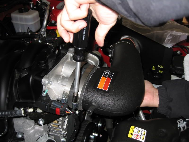
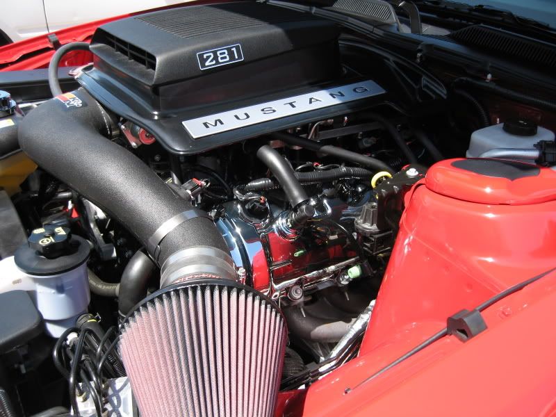
Remove the factory air intake or CAI.
Also, do not forget to disconnect the passenger side PCV hose and MAF sensor plug.
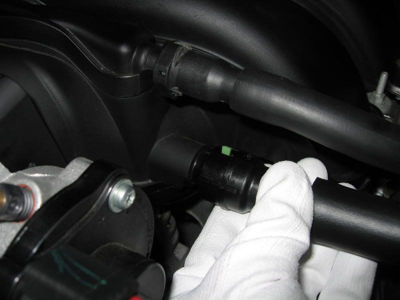
Slide the green release lever on the end clip of the PCV hose to the side and pull to disconnect (both ends, then set hose aside).

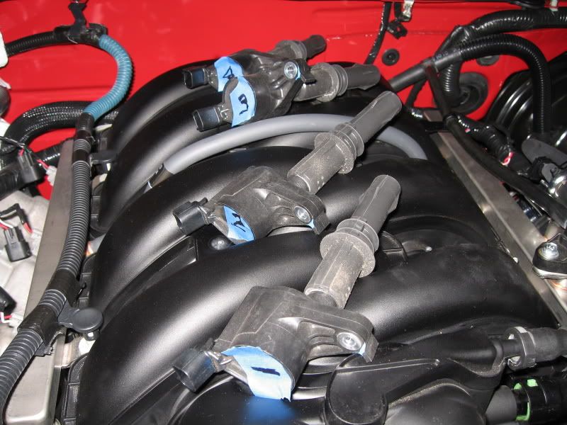
Remove the bolt using a 7mm socket that holds down the Coil On Plug (COP) to the cover; 4 places.
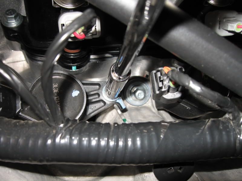
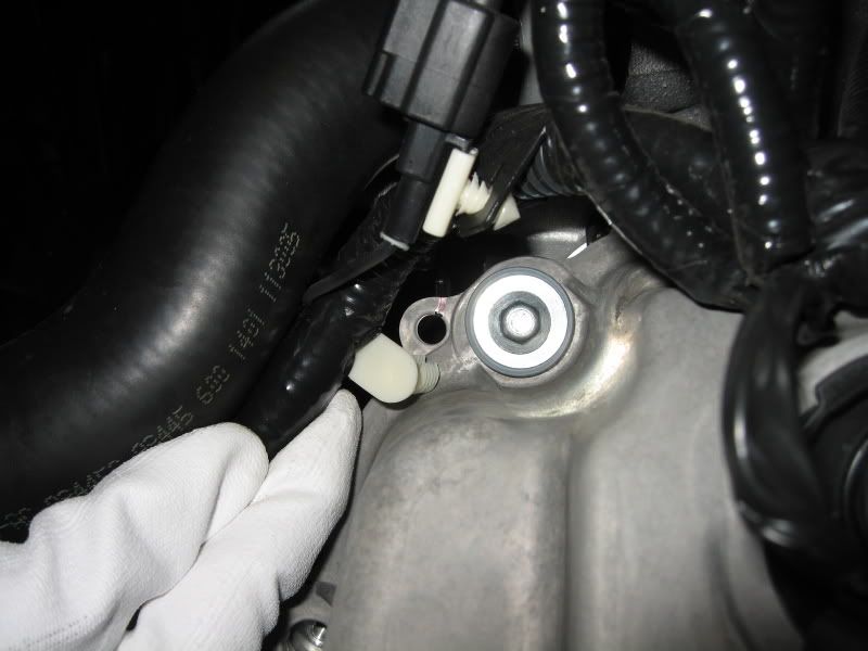
Disconnect the plug from the Variable Camshaft Timing Oil Control Solenoid.

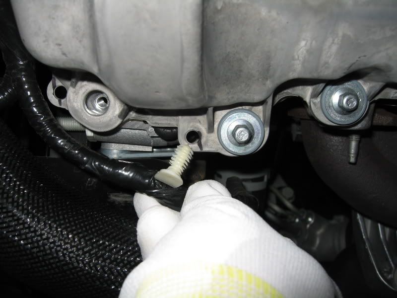
Pull the wire conduit support off from the cover studs.
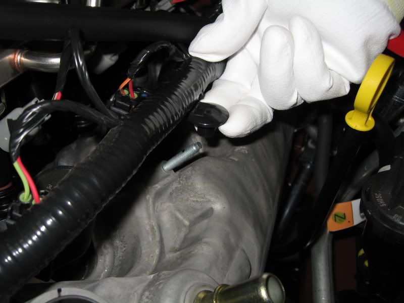
Pull the wire support clip up off from the cover; 2 places, top and bottom.
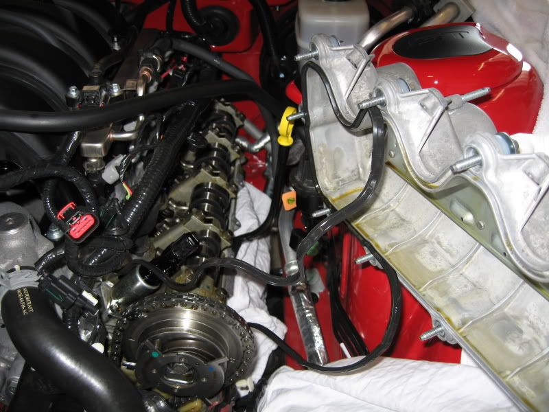
I placed a rag on top of the exhaust manifold to avoid spilling any oil directly on them when removing the cover.
Completely unscrew the 15 bolts from the cover using a 8mm socket.
Note: You do not need to pull the bolts completely off from the cover. There are rubber bushings on the bolt that will hold them in place.
Note: Use of a Universal Joint socket may aid in accessing some of the lower bolts.
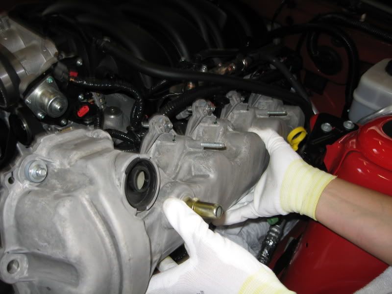
Once you're sure all the bolts are loose, carefully pull up on the cover, and with caution, guide it out from the car.
Note: Be careful of the VCTOC Solenoid (in the center of the black plug). The cover must be pulled straight up until it clears the end of the solenoid.
Note: You will notice that the black rubber gasket will pull away from the cover. This is because it'll be stuck to the RTV sealant at the front of the head.
Once the cover is free, carefully pull the gasket off from the sealant. (Care must be taken especially if you’re planning on reusing it; the FRPP kit will include new gaskets as well as new bolts)
Note: You can rotate the COP's (or unplug and remove them completely like what I did on the RH side) so they don't interfere with the cover as it's being removed.
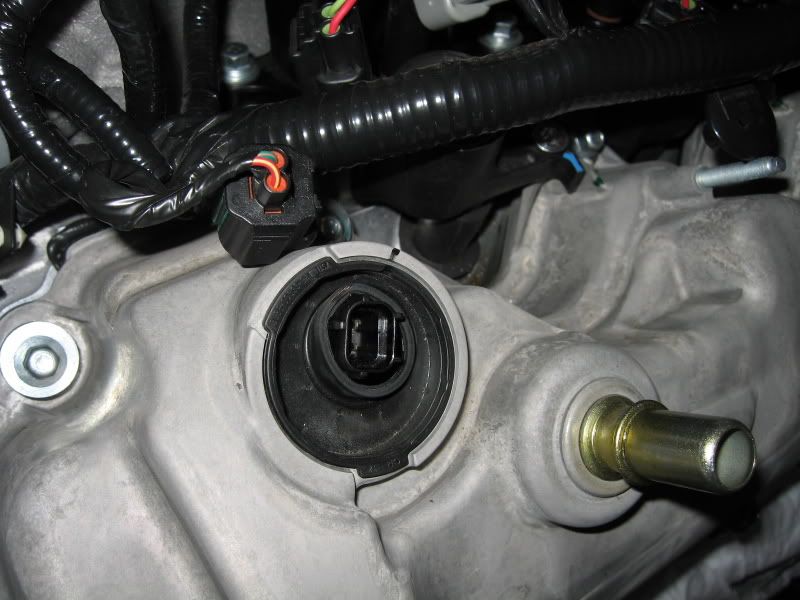
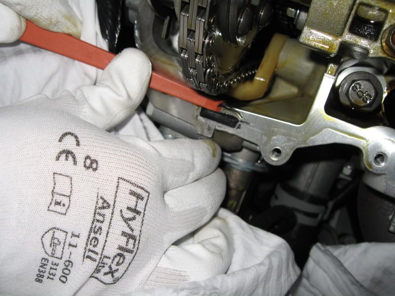
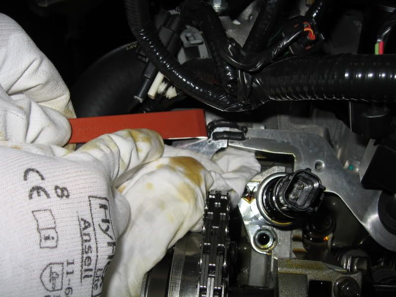
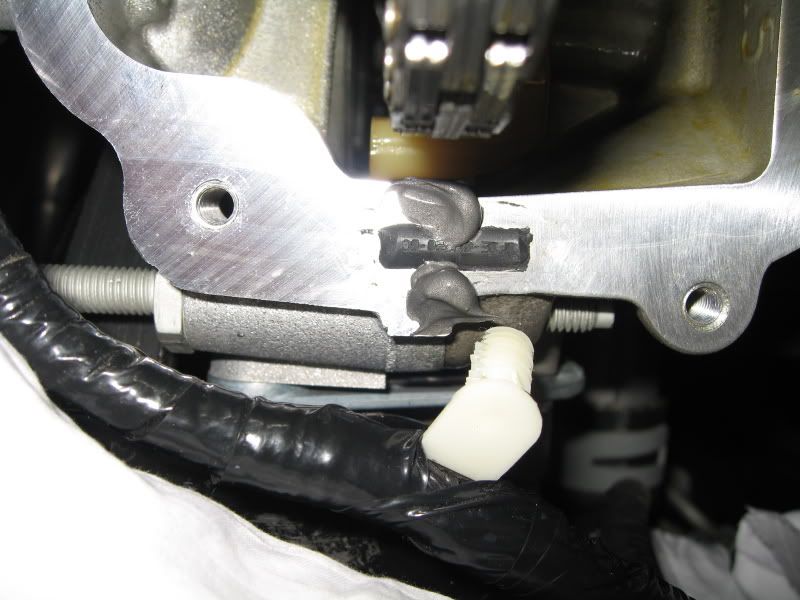
With a non-metallic scraper, carefully scrape the factory applied sealant off from where the head meets the forward engine cover (2 places, top and bottom).
Note: As you see from the pictures below, I only scraped off the upper and lower sealant globs and not the center rectangular rubber plug. I can't confirm if this was the correct thing to do, but to me, it looked like it was supposed to be there.
Note: Use caution in not letting the sealant pieces to fall into the head. I used a rag to catch the debris as I scraped it.
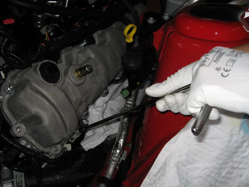
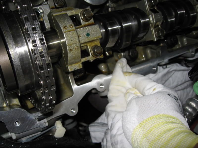
Using an appropriate solvent (I used brake cleaner), wipe the mating surface of the head.
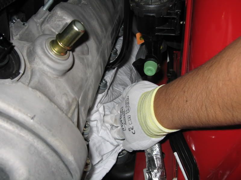
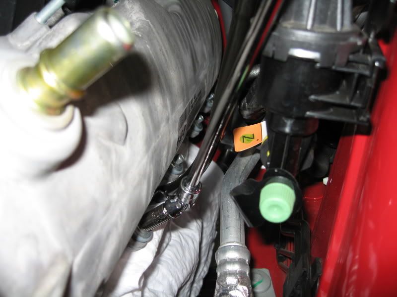
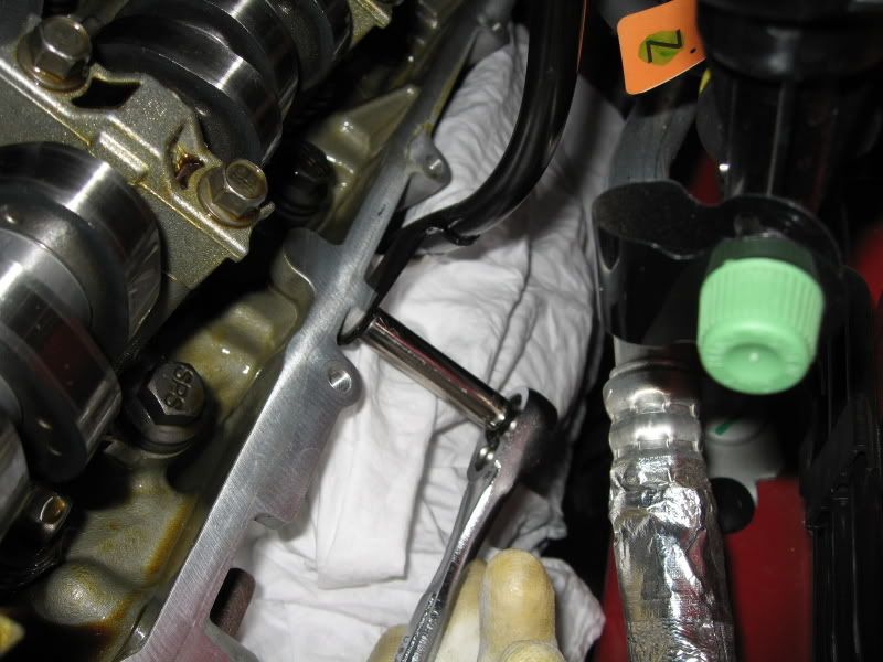
In anticipation of the new cover, I decided to give myself some additional room by loosening the oil dipstick tube. In hindsight, I should have loosened this bolt before removing the stock cover as it would've provided additional clearance.
Note: There's no need to remove the bolt completely, just far enough so the tube can be pushed to the side.
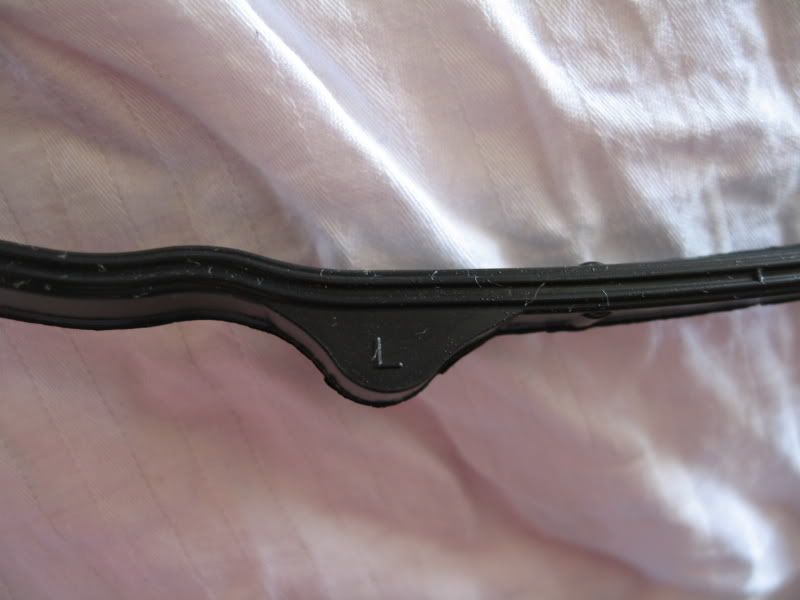
Side by side comparison shot.
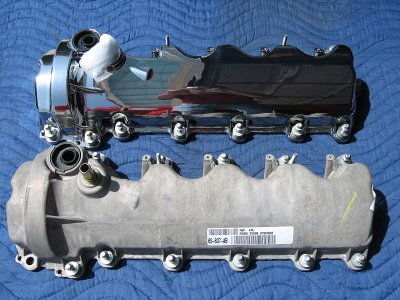
Each cover gasket is marked 'L' or 'R' on one of the indexing tabs. Without it, it can get a little confusing.
Clean off the gasket (whether new or reusing the old one) before installing it within the cover groove (I used isopropyl alcohol).
Also clean the inside of the groove of the cover where the gasket will seat into.
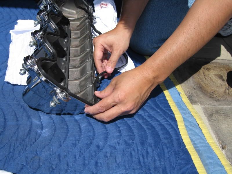
Carefully press in the gasket until it's completely seated all the way around.
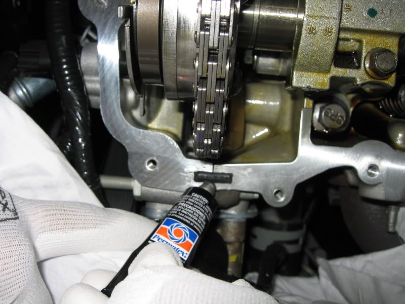
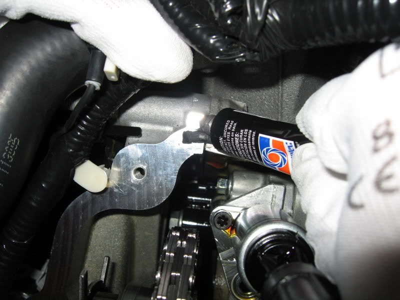
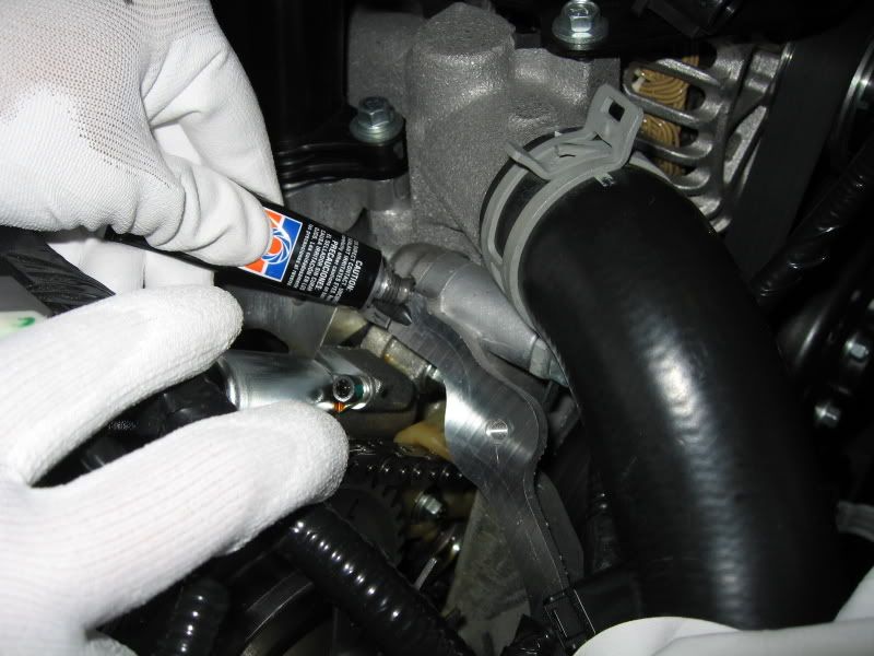
Apply a bead of RTV sealant at the same location directly on the seam where the head meets the front engine cover, top and bottom of that rectangular plug, 2 places.
Note: Per the sealant directions, the part must be installed within 4 minutes of application. Otherwise, it must be removed and re-applied.
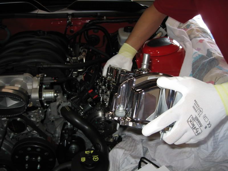
Getting ready to install the new cover!
Carefully guide the cover onto the head. Make sure the cover bolts are lined up before you press the cover down, especially over the freshly applied sealant.
Once down, start each bolt making sure you're not cross threading any of the bolts. Only lightly snug down all the bolts.
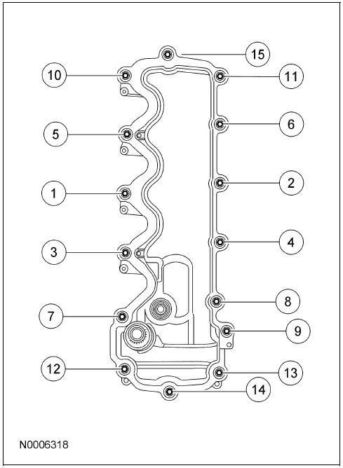
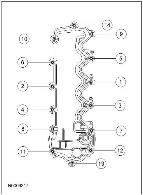
Using a torque wrench, torque each bolt in the sequence below to 89 lbs-in (That's inch pounds!)
Tighten the oil dipstick tube bolt, COP bolts, and re-connect everything that you removed or unplugged.
Driver's side complete!
(Passenger Side continued on post 2)
This 'How-To' will cover the removal and installation of valve/cam covers on the 4.6L.
I obtained this set from Tillman Speed.
I swapped my OEM covers with the FRPP ones. If you're planning on painting or powdercoating your covers, see the instructions at the end on how to remove the oil fill neck and plastic caps.
Drivers Side (LH)
Remove the factory air intake or CAI.
Also, do not forget to disconnect the passenger side PCV hose and MAF sensor plug.
Slide the green release lever on the end clip of the PCV hose to the side and pull to disconnect (both ends, then set hose aside).
Remove the bolt using a 7mm socket that holds down the Coil On Plug (COP) to the cover; 4 places.
Disconnect the plug from the Variable Camshaft Timing Oil Control Solenoid.
Pull the wire conduit support off from the cover studs.
Pull the wire support clip up off from the cover; 2 places, top and bottom.
I placed a rag on top of the exhaust manifold to avoid spilling any oil directly on them when removing the cover.
Completely unscrew the 15 bolts from the cover using a 8mm socket.
Note: You do not need to pull the bolts completely off from the cover. There are rubber bushings on the bolt that will hold them in place.
Note: Use of a Universal Joint socket may aid in accessing some of the lower bolts.
Once you're sure all the bolts are loose, carefully pull up on the cover, and with caution, guide it out from the car.
Note: Be careful of the VCTOC Solenoid (in the center of the black plug). The cover must be pulled straight up until it clears the end of the solenoid.
Note: You will notice that the black rubber gasket will pull away from the cover. This is because it'll be stuck to the RTV sealant at the front of the head.
Once the cover is free, carefully pull the gasket off from the sealant. (Care must be taken especially if you’re planning on reusing it; the FRPP kit will include new gaskets as well as new bolts)
Note: You can rotate the COP's (or unplug and remove them completely like what I did on the RH side) so they don't interfere with the cover as it's being removed.
With a non-metallic scraper, carefully scrape the factory applied sealant off from where the head meets the forward engine cover (2 places, top and bottom).
Note: As you see from the pictures below, I only scraped off the upper and lower sealant globs and not the center rectangular rubber plug. I can't confirm if this was the correct thing to do, but to me, it looked like it was supposed to be there.
Note: Use caution in not letting the sealant pieces to fall into the head. I used a rag to catch the debris as I scraped it.
Using an appropriate solvent (I used brake cleaner), wipe the mating surface of the head.
In anticipation of the new cover, I decided to give myself some additional room by loosening the oil dipstick tube. In hindsight, I should have loosened this bolt before removing the stock cover as it would've provided additional clearance.
Note: There's no need to remove the bolt completely, just far enough so the tube can be pushed to the side.
Side by side comparison shot.
Each cover gasket is marked 'L' or 'R' on one of the indexing tabs. Without it, it can get a little confusing.
Clean off the gasket (whether new or reusing the old one) before installing it within the cover groove (I used isopropyl alcohol).
Also clean the inside of the groove of the cover where the gasket will seat into.
Carefully press in the gasket until it's completely seated all the way around.
Apply a bead of RTV sealant at the same location directly on the seam where the head meets the front engine cover, top and bottom of that rectangular plug, 2 places.
Note: Per the sealant directions, the part must be installed within 4 minutes of application. Otherwise, it must be removed and re-applied.
Getting ready to install the new cover!
Carefully guide the cover onto the head. Make sure the cover bolts are lined up before you press the cover down, especially over the freshly applied sealant.
Once down, start each bolt making sure you're not cross threading any of the bolts. Only lightly snug down all the bolts.
Using a torque wrench, torque each bolt in the sequence below to 89 lbs-in (That's inch pounds!)
Tighten the oil dipstick tube bolt, COP bolts, and re-connect everything that you removed or unplugged.
Driver's side complete!
(Passenger Side continued on post 2)
Last edited by TacoBill; 3/14/08 at 02:10 PM. Reason: sp
 6/17/07, 09:04 AM
#2
Thread Starter
(Continued from post 1)
Passenger Side (RH)
Procedure is basically the same except what's noted below.
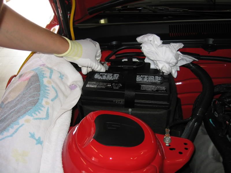
Remove the battery and tray.
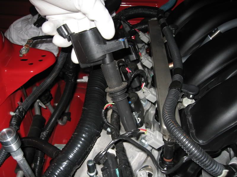
Going through a learning curve from the LH side, I decided to unplug the injector electrical plugs and remove the COP's completely. Doing so provided more than enough clearance to remove and install the cover.
I seriously doubt it makes any difference, but I decided to keep each COP assigned to its respective spark plug.
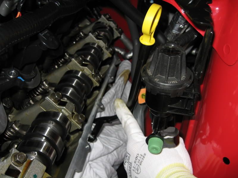
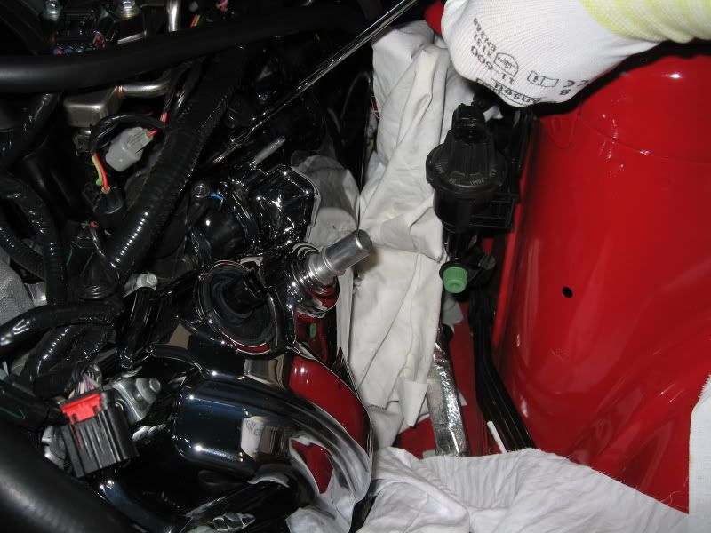
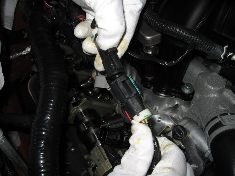
I disconnected this plug off from the main harness (near the front) so I can pull it further outboard when it's time to re-install the cover.
Once again, sealant was applied on the seam between the head and front engine cover. Same as the LH side.
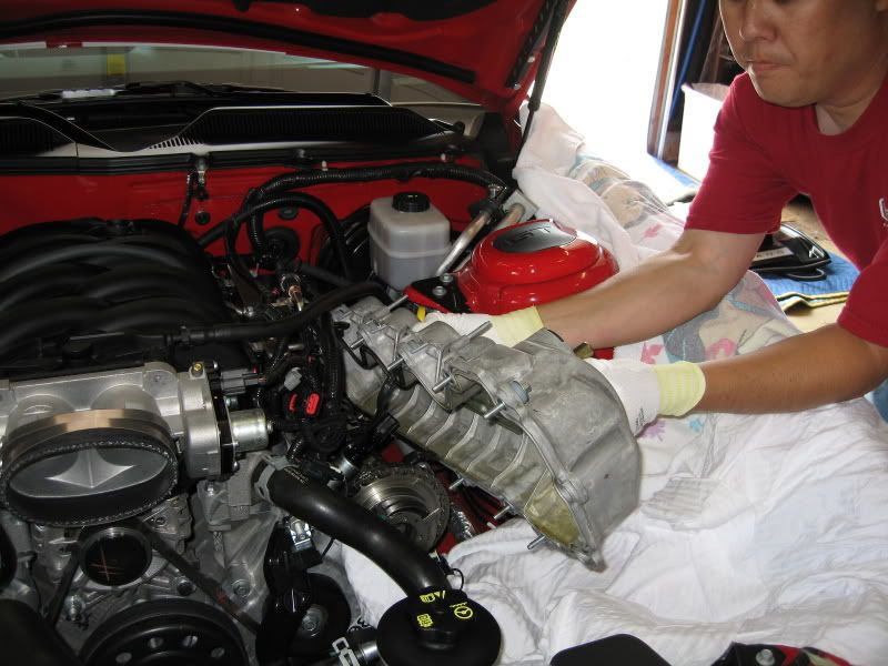
As you can see, with the harness pulled away, there was plenty of room to guide the cover into position.
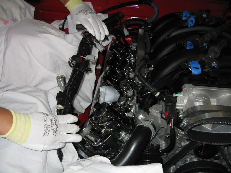
Using a torque wrench, torque each bolt in the sequence below to 89 lbs-in.
Note: Only 14 bolts are in the RH cover as opposed to 15 on the LH.
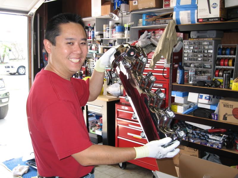
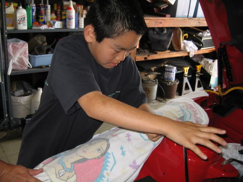
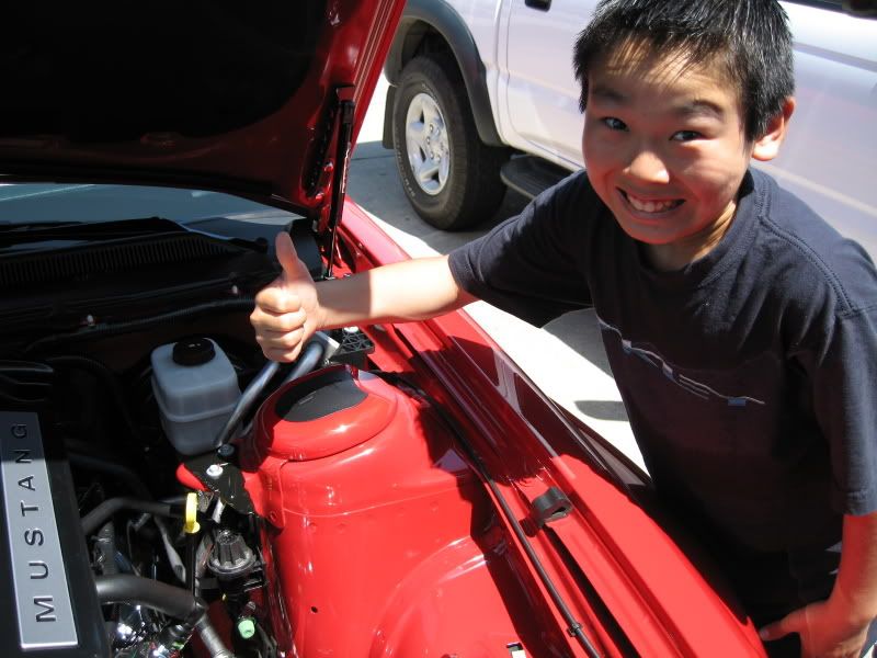
(Putting Chris to work)
Like the LH side, re-install the COP's, battery, and re-connect everything that you removed or unplugged (this includes the injector, COP, and VCTOC Solenoid plugs).
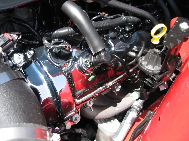
Installation complete!
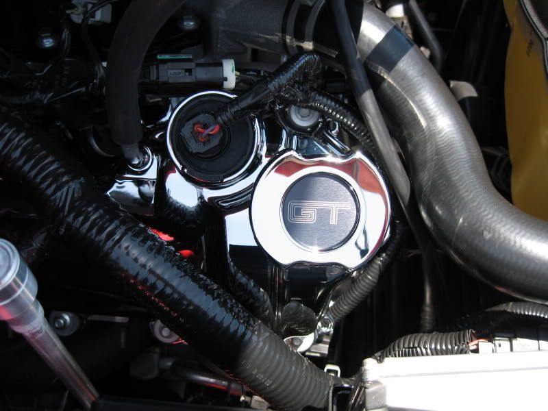
Note: I opted not to re-install the oil fill neck onto my FRPP cover. To me, the MGW oil cap looked much cleaner when installed directly onto the cover (same cam lock design).
Special Section
To those planning on either painting or having your covers powdercoated, you'll need to remove the oil fill neck and the black rubber/plastic plug for the cam sensor.
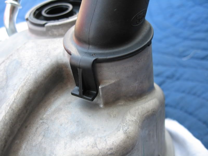
To remove the fill neck, carefully pry up on the plastic tab (I used a flat screwdriver) and slight rotate it until the tab clears from its locked position. Now, grasp the neck and forcefully turn in counter-clockwise to release it from the cover (cam type).
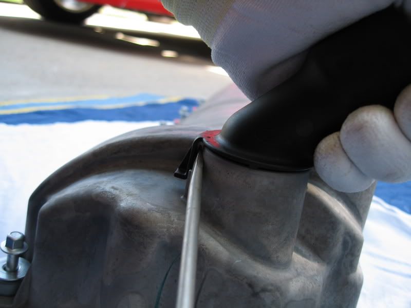
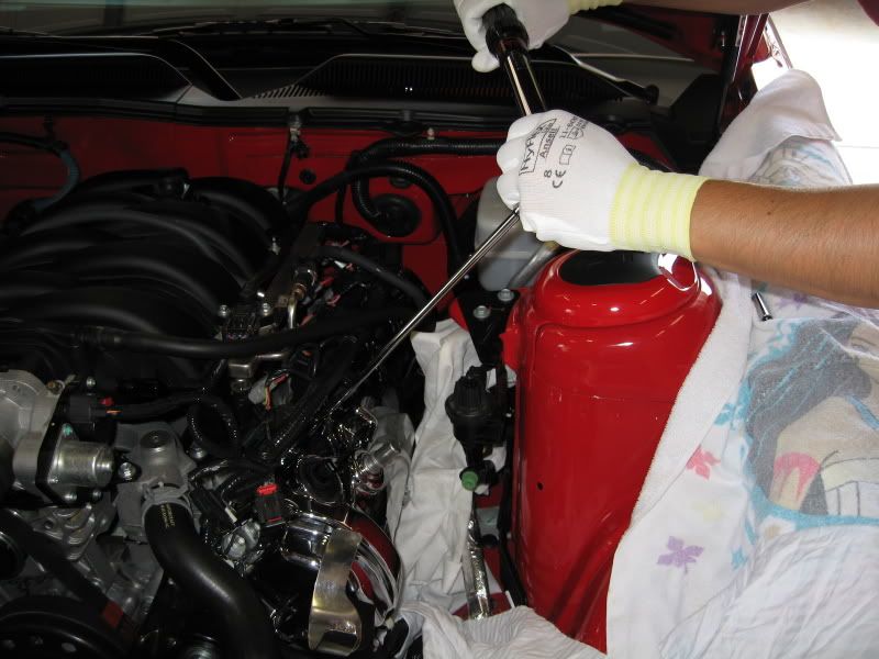
To remove the cam sensor plug, it must be removed from the inside-out.
I used the largest socket I had (1") along with an extension and a mallet.
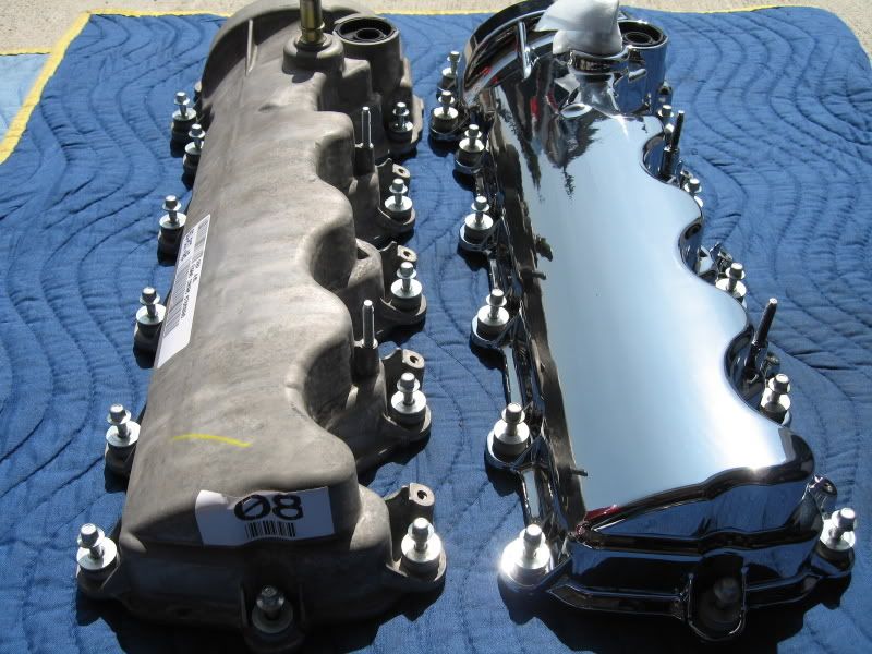
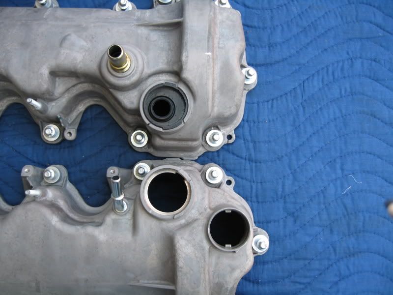
Here you can see both covers, one with and one without the VCTOC Solenoid plug. When re-installing the plug, simply press it in from the top aligning the notches.
Total time for my swap was around 3.5 hours, which included documentation.
Passenger Side (RH)
Procedure is basically the same except what's noted below.
Remove the battery and tray.
Going through a learning curve from the LH side, I decided to unplug the injector electrical plugs and remove the COP's completely. Doing so provided more than enough clearance to remove and install the cover.
I seriously doubt it makes any difference, but I decided to keep each COP assigned to its respective spark plug.
I disconnected this plug off from the main harness (near the front) so I can pull it further outboard when it's time to re-install the cover.
Once again, sealant was applied on the seam between the head and front engine cover. Same as the LH side.
As you can see, with the harness pulled away, there was plenty of room to guide the cover into position.
Using a torque wrench, torque each bolt in the sequence below to 89 lbs-in.
Note: Only 14 bolts are in the RH cover as opposed to 15 on the LH.
(Putting Chris to work)
Like the LH side, re-install the COP's, battery, and re-connect everything that you removed or unplugged (this includes the injector, COP, and VCTOC Solenoid plugs).
Installation complete!
Note: I opted not to re-install the oil fill neck onto my FRPP cover. To me, the MGW oil cap looked much cleaner when installed directly onto the cover (same cam lock design).
Special Section
To those planning on either painting or having your covers powdercoated, you'll need to remove the oil fill neck and the black rubber/plastic plug for the cam sensor.
To remove the fill neck, carefully pry up on the plastic tab (I used a flat screwdriver) and slight rotate it until the tab clears from its locked position. Now, grasp the neck and forcefully turn in counter-clockwise to release it from the cover (cam type).
To remove the cam sensor plug, it must be removed from the inside-out.
I used the largest socket I had (1") along with an extension and a mallet.
Here you can see both covers, one with and one without the VCTOC Solenoid plug. When re-installing the plug, simply press it in from the top aligning the notches.
Total time for my swap was around 3.5 hours, which included documentation.
Last edited by TacoBill; 3/14/08 at 02:12 PM. Reason: sp
6/17/07, 10:01 AM
#5
GT Member
Join Date: January 28, 2007
Posts: 136
Likes: 0
Received 0 Likes
on
0 Posts
6/17/07, 10:17 AM
#7
Legacy TMS Member
Join Date: January 9, 2005
Location: New Carlisle, Ohio (20 miles north of Dayton)
Posts: 6,982
Likes: 0
Received 6 Likes
on
6 Posts
Well Bill I am glad to see that at least the INSIDE of your engine is a little oily since it is pristine on the outside. I was thinking the whole time I was reading your install that "doesn't he have a CDC shaker"? Who will ever see them? I see where it looks as if you have trimmed you shaker back some. When did you do that? Outstanding write again Bill!
Scott
I was thinking the whole time I was reading your install that "doesn't he have a CDC shaker"? Who will ever see them? I see where it looks as if you have trimmed you shaker back some. When did you do that? Outstanding write again Bill! Scott
6/17/07, 10:31 AM
#8
Cobra Member
Good write up once again Bill.
What i am surprised about however is how good those covers look. I myself had ordered a set of the FRRP Chrome ones and when they showed up they looked terrible. They had debris stuck in the finish big runs what looked like paint on the underside where the gasket goes. Absolutely terrible product. I sent mine back and went with the Steeda Black Powder Coated ones and the fit and finish on them was far superior to the FRRP ones. The Steeda ones already had all gaskets installed and the gasket was far superior to the FRRP gasket which was merely thrown into the bottom of the box.
Glad to see yours seem to not have those issues.
Richard
6/17/07, 10:55 AM
#10
Thread Starter
Thanks guys! 
When I was considering this swap last year, I kept putting it off because I thought it would be a PITA to swap out. Actually turned out to be pretty simple.
Fixed. Thank you.
LOL! That vid was my 2nd take. I actually did struggle with it on the first take as took too long to remove. On the 2nd take (the one posted), it was much easier.
When I was considering this swap last year, I kept putting it off because I thought it would be a PITA to swap out. Actually turned out to be pretty simple.
LOL! That vid was my 2nd take. I actually did struggle with it on the first take as took too long to remove. On the 2nd take (the one posted), it was much easier.
6/17/07, 11:50 AM
#11
Shelby GT350 Member
Join Date: June 4, 2006
Location: McAllen, TX
Posts: 2,244
Likes: 0
Received 0 Likes
on
0 Posts
dang dude, you have the answers for everything, i think i am going to take off the filler neck for now and only use it when i need to go in for an oil change, i like having the look of a cobra motor with that mod
6/17/07, 11:52 AM
#12
Legacy TMS Member
Good deal Bill..... FWIW, my covers were supposed to be done yesterday but I couldn't get off of work in time to pick them up before they closed. Should have them tomorrow, and hope to have them installed tomorrow night!!
6/17/07, 03:53 PM
#17
Cobra Member

Join Date: May 17, 2007
Location: Texa$
Posts: 1,201
Likes: 0
Received 0 Likes
on
0 Posts
 To funny
6/17/07, 06:51 PM
To funny
6/17/07, 06:51 PM
#18
Team Mustang Source
Join Date: June 19, 2004
Location: Phoenixville, PA
Posts: 6,840
Likes: 0
Received 2 Likes
on
2 Posts
Bill, fabulous write-up as always. Its perfect timing, as I just purchased a brand new set of Blue Crinkle powdercoated valve covers from a fellow TMS'er who couldn't use them anymore (got a Shelby GT, and doesn't want to modify it. I can't blame him, its a HOT car!). I have the Mustang Monthly article where they install theirs, but your install instructions are FAR superior. Thanks for the great work. Can't wait to put mine on next weekend!